INSTALL GATE FRAMES
STEP 1 / MEASURE
Measure width between posts
If installing a SINGLE GATE:
- Allow 5mm to 10mm clearance between the gate and the post for the hinges.
If installing a DOUBLE GATE:
- Allow 5mm to 10mm clearance between each gate and its post on each side.
- Allow 10mm to 15mm clearance between where the left and right gates meet.

Measure height of support posts
- If the ground is levelled, allow for 50mm clearance under the gate.
- If the ground is unlevelled, then a taller clearance under the gate may be required.
STEP 2 / CHOOSE
Gate Chooser
Plug your measurements into the below fields to help you select the most suitable products for your project.
STEP 3 / SWING DIRECTION
Decide how you want the gate to swing
If installing INWARD SWINGING GATE:
- Fix hinges to BACK of the support post
If installing OUTWARD SWINGING GATE:
- Fix hinges to FRONT of the support post
If installing a SINGLE GATE:
- You will also need to decide if your gate will swing from the LEFT or RIGHT post.


Check orientation of hinges
Hold the hinge section of the frame up against the BACK of the post, and ensure that:
- Plastic cap is at top.
- Hinge opening faces down.
- If hinges are upside down – you can reverse them to fit your desired swing direction.
Fortress Gates Hinges are designed to be REVERSIBLE – so they can swing from a Left Hand or Right Hand post.
If your hinge is upside down (cap at bottom and opening at top) you will need to reverse it.
To reverse the hinge:
- Remove the plastic oil cap to expose the ball bearing.
Please note, the ball bearing is held captive within the hinge barrel. It can move from end to end but cannot come out. - Place end-of-hinge pin against the ball bearing
- Use a mallet or heavy block of wood to hit the hinge pin and dislodge the ball bearing from its retaining groove.
Do not use a metal hammer as it may burr the end of the hinge pin. This may take a good solid hit. - Tap ball bearing down until it snaps into the retaining groove at the other end.
- Insert the plastic oil cap at the top section of the hinge to cover the ball bearing (the opposite end to where it was inserted before).


STEP 4 / ASSEMBLE
- Place one side of the frame on firm ground – slide rails on.
- If necessary use a mallet or block of wood to BUMP the rails on – do not use a metal hammer.
- Bump the other side of the frame into place.
- Secure the frame together using the Self-Drilling Screws supplied.
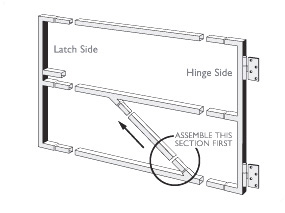
Whether your gate needs a brace or not will depend on the width and the type of cladding used. Generally speaking frames wider than 1.2m should have a diagonal brace. Some cladding such as Colourbond Sheeting will act as a brace once it is secured to the frame.
The brace starts at the Latch side and runs downwards to the bottom hinge. This is so that the brace joints are under compression and cannot come apart.
What if my brace doesn’t fit?
Assemble the ‘Z’ shaped brace section first otherwise your frame will not go together.
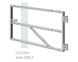
What if my frame is too wide?
Approximately 300 mm can be cut off the width of our “HD” labelled products.
CAUTION – do not cut the wrong end of the brace or the frame could be ruined. Only cut back on the latch side.


STEP 5 / CLAD
Finish with your choice of cladding.
- Drill hole in the timber only.
- Place Self-Drilling Screw in the hole in timber.
- Screw directly into the steel frame using an electric drill.

